Welcome to our web page, where you can access an interactive Dip Switch Calculator for DMX lighting systems. Our intuitive tool simplifies the process of configuring dip switch settings, allowing you to find the correct binary representation for your desired DMX address effortlessly. Say goodbye to manual calculations and ensure precise configurations for your lighting fixtures with ease. Let’s make DMX control a breeze with our user-friendly Dip Switch Calculator.
Dip Switch Calculator
What is a Dip Switch Calculator?
A Dip Switch Calculator is a tool used to find the correct configuration of dip switches for a certain address setting in a DMX (Digital Multiplex) lighting control system. DMX is a digital control protocol commonly used for lighting control in various applications, including stage lighting, show laser lights, and other entertainment systems.
DMX512, the most widely used version of the DMX protocol, operates with a serial signal and requires setting a unique start address for each lighting fixture or device in the DMX line. This address determines how the control signal will be sent to a specific device within the DMX network.
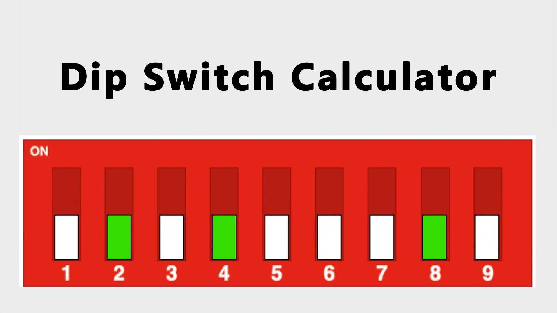
Dip switches are physical switches typically found on the lighting fixtures. Each switch represents a binary digit (0 or 1), and the combination of these binary digits determines the DMX address for that particular device. For example:
- Switch 1 represents the value 1 (2^0 = 1).
- Switch 2 represents the value 2 (2^1 = 2).
- Switch 3 represents the value 4 (2^2 = 4).
- Switch 4 represents the value 8 (2^3 = 8).
- And so on…
To configure the DMX address on a device, the Dip Switch Calculator helps users find the correct dip switch settings based on the desired DMX address value. Users enter the desired DMX address value into the calculator, and it calculates the binary representation of the value and provides instructions on how to set the dip switches accordingly.
Example
For example, if a user wants to set a DMX address value of 11, the calculator will show that the dip switch configuration should be 11010000, as follows:
- Switch 1: OFF (0)
- Switch 2: ON (1)
- Switch 3: OFF (0)
- Switch 4: ON (1)
- Switch 5: OFF (0)
- Switch 6: OFF (0)
- Switch 7: OFF (0)
- Switch 8: OFF (0)
- Switch 9: OFF (0)
- Switch 10: OFF (0)
By setting the dip switches accordingly, the lighting fixture will be assigned the DMX address value of 11 and will respond to control signals sent on that address.
The Dip Switch Calculator simplifies the process of configuring DMX addresses for lighting fixtures, making it easier for users to set up their lighting control systems accurately.
Electrical engineer Xun Pang helped to create this calculator. He gave us instructions. Moreover, he also validated the performance and accuracy of this calculator.
How does this Dip Switch Calculator work?
This Dip Switch Calculator works by taking a decimal DMX address value as input and converting it into its binary representation, which corresponds to the dip switch configuration needed to set that specific DMX address on a lighting fixture or device.
Working procedure of Dip switch calculator
Here’s how the Dip Switch Calculator works step by step:
User Input:
The user enters the desired DMX address value into the calculator. For example, the user may enter “11” if they want to set a DMX address of 11 for a lighting fixture.
Binary Conversion:
The calculator converts the decimal DMX address value into its binary representation. It does this by repeatedly dividing the decimal number by 2 and keeping track of the remainders. Each remainder corresponds to a binary digit (0 or 1). The remainders are read in reverse order to get the binary representation.For example, for a DMX address value of 11:
- 11 divided by 2 gives a quotient of 5 and a remainder of 1 (LSB, Least Significant Bit).5 divided by 2 gives a quotient of 2 and a remainder of 1.2 divided by 2 gives a quotient of 1 and a remainder of 0.1 divided by 2 gives a quotient of 0 and a remainder of 1 (MSB, Most Significant Bit).
Padding:
Since the DMX address is represented by 10 dip switches (even if the 10th switch is not used), the binary representation needs to be padded with leading zeros to ensure it has a length of 10 digits.For example, the binary representation of 11, which is 1011, needs to be padded with leading zeros to become 0000001011.
Dip Switch Configuration:
The calculator now presents the binary representation, with each binary digit corresponding to the status of a dip switch. If a binary digit is “1,” the corresponding dip switch should be set to ON, and if it’s “0,” the dip switch should be set to OFF.For example, the dip switch configuration for DMX address 11 (binary 0000001011) is as follows:
- Switch 1: OFF (0)Switch 2: OFF (0)Switch 3: OFF (0)Switch 4: OFF (0)Switch 5: OFF (0)Switch 6: OFF (0)Switch 7: ON (1)Switch 8: OFF (0)Switch 9: ON (1)Switch 10: ON (1)
Summary of the working procedure of the Dip switch calculator
The Dip Switch Calculator simplifies the process of manually setting the dip switches for specific DMX address values, ensuring that lighting fixtures are correctly configured and respond to control signals on the desired address.
What is a dip switch garage door opener?
A dip switch garage door opener is an older type of garage door opener that uses dip switches to set the communication code between the remote control and the garage door opener motor.
Here’s how a dip switch garage door opener works:
- Dip Switches: Both the garage door opener motor and the remote control have a set of small switches known as “dip switches.” These dip switches typically come in pairs, where one switch is for setting the ON/OFF position, and the other is for a security feature (which is not used in all models).
- Code Setting: During the installation or programming process, you must set the dip switches on the garage door opener motor and the remote control to match the same sequence. The dip switch positions represent a binary code that identifies the unique communication code between the remote and the opener motor.
- Transmission: When you press a button on the remote control, it transmits the binary code corresponding to the dip switch positions. The garage door opener motor receives this signal and compares it with its own dip switch settings.
- Opening the Door: If the transmitted binary code matches the dip switch settings on the motor, the opener interprets it as a valid signal from an authorized remote control and opens or closes the garage door accordingly.
While dip switch garage door openers were common in the past, they are not as secure as newer technologies. The main vulnerability is that the code remains fixed unless manually changed. If someone else has a remote control with the same dip switch settings, they can easily open the garage door, which poses a security risk.
Due to these security concerns, modern garage door openers have largely shifted to more advanced technologies like rolling code or frequency hopping, which change the transmitted code with each use, making unauthorized access much more challenging. If you have an older dip switch garage door opener, you may want to consider upgrading to a more secure system for improved security.
Dip switch settings
Dip switch settings are configurations used to set specific parameters or options on various electronic devices or systems. The settings are adjusted by toggling physical dip switches on the device, with each switch representing a binary digit (0 or 1). The combination of these binary digits determines the overall configuration.
Here’s how dip switch settings generally work:
- Dip Switches: A dip switch is a small switch with two possible positions, usually labeled ON and OFF or 1 and 0. The number of dip switches available varies depending on the device’s complexity and the number of configuration options required.
- Binary Representation: Each dip switch corresponds to a specific binary value. For example, if a dip switch is ON, it represents a binary 1, and if it is OFF, it represents a binary 0. The position of each dip switch determines the binary value it contributes to the overall configuration.
- Decimal to Binary Conversion: If a device has multiple dip switches, their binary values are combined to form a decimal number that represents the desired configuration. For instance, if you have four dip switches, you can represent values from 0 to 15 (2^4 – 1) by toggling the switches ON and OFF in different combinations.
- Configuring the Device: Once you determine the decimal value corresponding to the desired configuration, you set the dip switches accordingly. For example, if the device’s manual instructs you to set the dip switches to “5,” you convert “5” to binary, which is “0101,” and then set the dip switches accordingly (OFF-ON-OFF-ON).
Dip switch settings are commonly found on various electronic devices, including:
- Remote controls (e.g., garage door openers, TV remotes)
- Network devices (e.g., routers, switches)
- Peripheral devices (e.g., printers, scanners)
- Audio equipment (e.g., mixers, amplifiers)
- Industrial control systems
- Electronic toys and gadgets
Examples of DMX address to binary outputs
Here are the examples of DMX addresses to converted binary output values:
| DMX Address (Decimal) | Binary Output |
|---|---|
| 1 | 0000000001 |
| 5 | 0000000101 |
| 10 | 0000001010 |
| 25 | 0000011001 |
| 32 | 0000100000 |
| 50 | 0000110010 |
| 75 | 0001001011 |
| 100 | 0001100100 |
| 128 | 0010000000 |
| 150 | 0010010110 |
| 175 | 0010101111 |
| 200 | 0011001000 |
| 225 | 0011100001 |
| 250 | 0011111010 |
| 255 | 0011111111 |